|
||||||||||||||||||
|
|
|
|
|
|
|
|
|
|
|
|||||||||
|
|
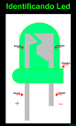
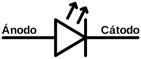
Led (Mais curto negativo) |
|
|
|
|
|
||||||||||||
|
|
|
|
|
|
|
|
|
|
|
|||||||||
|
|
|
|
|
|
|
|
|
|
|
|||||||||
|
|
|
|
|
|
|
|
|
|
|
|||||||||
|
|
|
|
|
|
|
|
|
|
|
|||||||||
|
|
|
|
|
|
|
|
|
|
|
|||||||||


|
|
|
|
|
|
Um potenciómetro (português europeu) é um componente eletrônico que possui resistência elétrica ajustável. Geralmente, é um resistor de três terminais onde a conexão central é deslizante e manipulável. Se todos os três terminais são usados, ele atua como um divisor de tensão.1 Existem comercialmente, potenciômetros confeccionados com substrato em fio e carvão condutivo, a depender da corrente elétrica que circula nestes. Há potenciometros cujo giro é de 270 graus e outros de maior precisão chamados multivoltas. Em relação à curva de resposta em função do ângulo de giro do eixo, existem dois tipos de potenciómetros, os lineares (sufixo B ao final do código) e os logarítmicos (sufixo A ao final do código comercial do valor). Exemplo de especificação de potenciômetro linear: 50 KΩ, ou seja, de 50.000 ohms, linear. Os potenciômetros lineares possuem curva de variação de resistência constante (linear) em relação ao ângulo de giro do eixo. Os potenciômetros logarítmicos, por sua vez, apresentam uma variação de resistência ao ângulo de giro do eixo mais adaptada à curva de resposta de audibilidade do ouvido humano. Considerando um aparelho de som, os potenciometros lineares são recomendados para uso em controle de tonalidade (graves, médios e agudos) já os logarítmicos são mais recomendados para controles de volume. http://pt.wikipedia.org/wiki/Potenci%C3%B4metro |
|
|
|
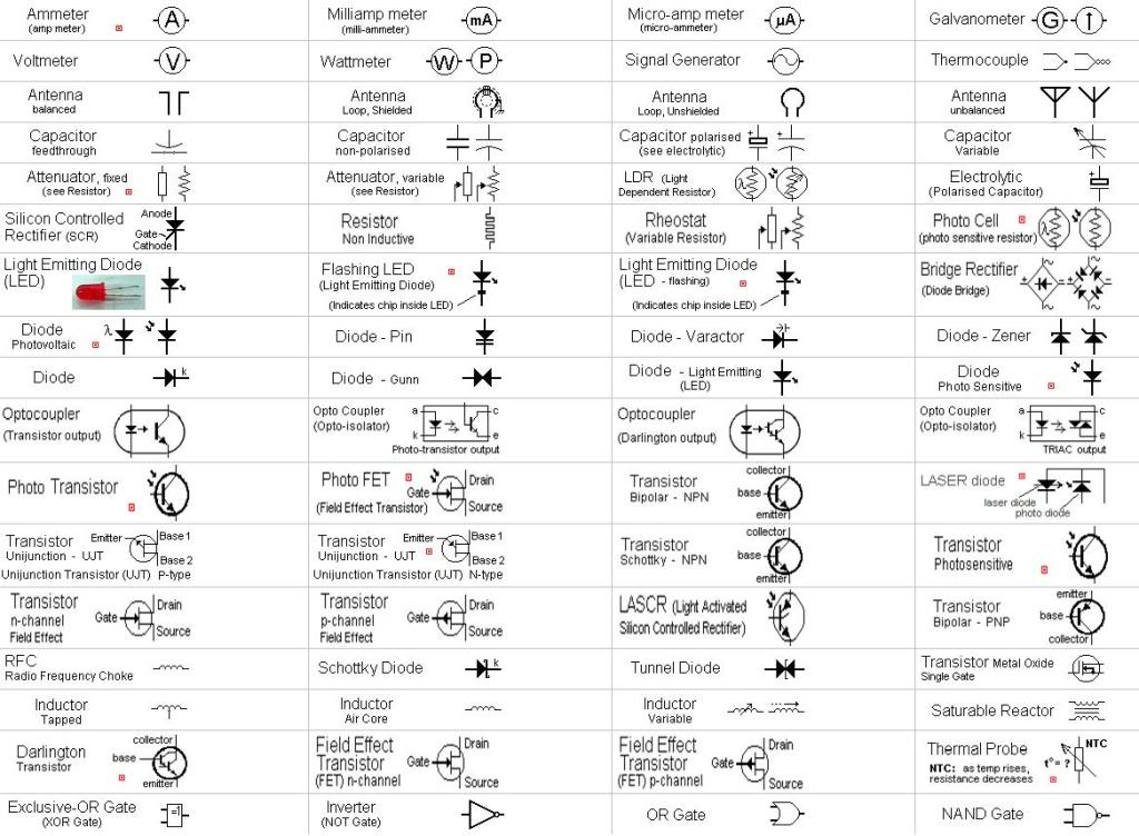
O diodo emissor de luz, também conhecido pela sigla em inglês LED (Light Emitting Diode), é usado para a emissão de luz em locais e instrumentos onde se torna mais conveniente a sua utilização no lugar de uma lâmpada. Especialmente utilizado em produtos de microeletrônica como sinalizador de avisos, também pode ser encontrado em tamanho maior, como em alguns modelos de semáforos. Também é muito utilizado em painéis de led, cortinas de led e pistas de led.nota 1 Em 7 de outubro de 2014, os inventores dos diodos emissores de luz azul foram laureados com o Prêmio Nobel de Física.3 |
|
|
|
|
|
|
|
What's The Difference Between DC, Servo & Stepper Motors? Need a motor for your project, but not sure which type to get? We
stock a few different varieties on ModMyPi, so hopefully this rundown on the difference between DC, Servo
and Stepper Motors will help you decide! DC Motors DC (Direct Current) Motors are two wire
(power & ground), continuous rotation motors. When you supply power, a DC
motor will start spinning until that power is removed.
Most DC motors run at a high RPM (revolutions per minute), examples being
computer cooling fans, or radio controlled car wheels! The speed of DC motors is controlled using
pulse width modulation (PWM), a technique of rapidly pulsing the power on and
off. The percentage of time spent cycling the on/off ratio determines the
speed of the motor, e.g. if the power is cycled at 50% (half on, half off),
then the motor will spin at half the speed of 100% (fully on). Each pulse is
so rapid that the motor appears to be continuously spinning with no
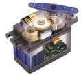
stuttering! Servo Motors Servo motors are generally an assembly of four things: a DC motor,
a gearing set, a control circuit and a position-sensor (usually a
potentiometer). The position of servo motors can be
controlled more precisely than those of standard DC motors, and they usually
have three wires (power, ground & control). Power to servo
motors is constantly applied, with the servo control circuit
regulating the draw to drive the motor. Servo motors
are designed for more specific tasks where position needs to be defined
accurately such as controlling the rudder on a boat or moving a robotic arm
or robot leg within a certain range. Servo motors do not rotate freely like a standard DC motor. Instead the angle of
rotation is limited to 180 Degrees (or so) back and forth. Servo
motors receive a control signal that represents an output position and
applies power to the DC motor until the shaft turns to the correct position,
determined by the position sensor. PWM is used for the control signal of servo motors.
However, unlike DC motors it’s the duration of the
positive pulse that determines the position, rather than speed, of the servo
shaft. A neutral pulse value dependant on the servo
(usually around 1.5ms) keeps the servo shaft in the centre
position. Increasing that pulse value will make the servo turn clockwise, and
a shorter pulse will turn the shaft anticlockwise. The servo control pulse is
usually repeated every 20 milliseconds, essentially telling the servo where
to go, even if that means remaining in the same position. When a servo is commanded to move, it will
move to the position and hold that position, even if external force pushes
against it. The servo will resist from moving out of that position, with the
maximum amount of resistive force the servo can exert being the torque rating
of that servo. Stepper Motors A stepper motor is essentially a servo motor that uses a different method of motorisation. Where a servo motor
uses a continuous rotation DC motor and integrated controller circuit,
stepper motors utilise multiple toothed
electromagnets arranged around a central gear to define position. Stepper motors require an external control circuit or micro controller
(e.g. a Raspberry Pi or Arduino) to individually energise
each electromagnet and make the motor shaft turn. When electromagnet ‘A’ is powered it attracts the gear’s teeth and aligns them,
slightly offset from the next electromagnet ‘B’. When ‘A’ is switch off, and
‘B’ switched on, the gear rotates slightly to align with ‘B’, and so on
around the circle, with each electromagnet around the gear energising and de-energising in
turn to create rotation. Each rotation from one electromagnet to the next is
called a "step", and thus the motor can be turned by precise
pre-defined step angles through a full 360 Degree
rotation. Stepper motors are available in two varieties;
unipolar or bipolar. Bipolar motors are the strongest type of stepper motor
and usually have four or eight leads. They have two sets of electromagnetic
coils internally, and stepping is achieved by
changing the direction of current within those coils. Unipolar motors,
identifiable by having 5,6 or even 8 wires, also
have two coils, but each one has a centre tap.
Unipolar motors can step without having to reverse the direction of current
in the coils, making the electronics simpler. However, because the centre tap is used to energise only half of each coil at a time they typically
have less torque than bipolar. The design of the stepper motor provides a constant holding torque
without the need for the motor to be powered and, provided
that the motor is used within its limits, positioning errors don't
occur, since stepper motors have physically pre-defined stations. Summary This is a rather condensed overview of a
complicated and somewhat disputed field (especially regarding the pros and
cons of stepper vs servo!), but hopefully it should help you make a more
informed choice with your motoring needs! DC Motors Fast, continuous rotation motors – Used for
anything that needs to spin at a high RPM e.g. car wheels, fans etc. Servo Motors Fast, high torque, accurate rotation within
a limited angle – Generally a high performance alternative to stepper motors,
but more complicated setup with PWM tuning. Suited for robotic arms/legs or
rudder control etc. Stepper Motors Slow, precise rotation, easy set up &
control – Advantage over servo motors in positional
control. Where servos require a feedback mechanism and support circuitry to
drive positioning, a stepper motor has positional control via its nature of
rotation by fractional increments. Suited for 3D printers and similar devices
where position is fundamental. https://www.modmypi.com/blog/whats-the-difference-between-dc-servo-stepper-motors |
|
|
|
|
|
|
|
|
|
|
|
|
|

|
|
|
|
|
|
|
Dupont
Jumper Wire |
|
|
|
|
|
Prototype
PCB |
|
|
|
|
|
safety
trip switch double pole |
|
|
|
|
|
Safety
Switch Caravan RV Double Pole 16 Amp 4.5kA with 2 Module Enclosure 2 pole |
|
|
|
|
|
SPDT 3
Pins Toggle Switch AC 125V 6A ON/ON 2 Position |
|
|
|
|
|
|
|
|
|
|
|
|
|
|
|
|
|
|
|
|
|
|
|
|
|
|
|
|
|
|
|
|
|
|
|
|
|
|
|
|
|
|
|
|
|
|
|
|
|
|
|
|
|
|
|
|
|
|
|
|
|
|
|
|
|
|
|
|
|
|
|
|
|
|
|
|
|
|
|
|
|
|
|
|
|
|
|
|
|
|
|
|
|
|
|
|
|
|
|
|
|
|
|
|
|
|
|
|
|
|
|
|